Engineering 

Team

A place where people fall short is building their team. They choose friends or people that they think they would have the most fun with. Personally I believe in choosing the right people for the job that have the skills or have a stronger desire to be strong players of a team. Personally I do not leave these things to chance, I went out of my way to find the best people for my team, I was researching candidates while everyone was still enjoying their summer vacation. I wanted to win so I planed to win. I was not surprised when my team and I won the design competition at the end of the year. 

The Problem

Disabled People with Muscular Dystrophy and other similar diseases have dexterity issues. This prevents them from doing activities like drawing, painting, or using a computer mouse properly. These activities require fine finger dexterity.

The Must Have solutions

To allow these people to draw or paint, a tool or machine is required. The product must:
Be comfortable to use
Easy to operate
Be Aesthetically Pleasing
Correct jittery drawing motion into precise one

The Scope of the Project

Designing and fabricating a compact, accessible drawing robot allowing disabled people to draw with ease using a controller.

Research Phase

Key Requirement, this required creating a specification document and doing research on similar products, creating sketches to try and map out which direction should be taken in order to create a product that satisfies not only the needs of the end user but of the client. 

Design happens in layers like a onion. 

Design Requirements

Functional Requirements

  • Drawing Robot Assembly1
    • The drawing robot shall draw linear and nonlinear paths using a pencil, based on input form joystick and motion buttons on the control panel.
    • The assembly shall consist of the main-body, 2-bar linkage, control panel, joystick, and drawing board.
    • The drawing robot shall use a 2-bar linkage, and the SCARA coordinate system to traverse in the (x, y) plane.
    • The assembly shall be capable of lifting the pencil vertically before translating in (x, y) plane.
  • Weight
    • The assembly should weigh less than 3kg.
    • Joystick controllers shall weigh less than 500g.
  • Component Functions and Dimensions
    • Drawing Board2
      • Shall be used to paint on with the paintbrush.
      • Shall contain a paint palette, with at least 4 colours.
      • Shall contain a small water container for cleaning brush tip.
      • Shall have an 8.5” x 11” flat surface to draw and paint on.
      • Should be 14.5” x 12.5” x 4/10”.
    • Touch Pad3
      • The touchpad shall be used for translating pencil in (x, y) plane with fingertip motion on its surface.
      • Shall translate input data via sensors to output signals to move the robot arm.
      • Should be 5”x 4” x 0.3”.
    • Main body and Housing
      • Shall provide the structure for containing stepper motors, servos, PCB, and bar-linkage.
      • Shall have enough space to fit motors, PCB, and control mechanisms.
      • Shall contain ON/OFF switch on the outside.
      • Shall use a Two-Bar linkage to control (x, y) translation of the pencil.
        • The two-bar linkage shall be no longer than 8in
      • Should be 5” x 2” x 5”
    • Joystick
      • The joystick shall be rotated in any direction, by a human hand, to move the pencil in the (x, y) plane.
      • Shall move the pen faster when the joystick shaft is rotated further.
      • Shall translate input data from shaft into output signals to the Arduino.
      • Should not exceed the dimensions 3.5” x 3.5” x 3.5”.
    • Control Panel
      • The control panel shall be a board with buttons that provide (x, y) translation of the pencil as well as vertical lift of the pen.
      • Shall contain multiple sources of inputs and translate output data to Arduino.
      • Should be 12” x 6” x 3”.
    • Actuation Forces
      • Joystick must actuate with a maximum force of 101.97 gf/1 N.
      • All controller switches must actuate with a maximum force of 51 gf/0.5 N.
    • Information Flow
      • Shall use Switches, Joysticks, TouchPad and Control Panel.
    • Control Systems
      • Shall use Stepper motors or Servo Motors.
      • Shall use a SCARA coordinate system for coordinate location.
    • Power Source/Data Transfer
      • Input power (AC) shall be converted into 12V DC current using an adapter and sent to Arduino.
      • Joystick controllers should send data to robot microcontrollers via USB.
      • Joystick controllers should receive DC power from a microcontroller via USB.
  1. Safety Requirements
    • Voltage and Current shall be limited to 12 Volts and 1300mA.
    • Product shall have a smooth finish with no sharp edges.
    • The power adapter shall be CSA approved.
  2. Quality
    • Product shall be durable and be able to withstand impact from a minimum of 1.5m fall on concrete.
    • Joystick shaft shall not bend/fracture under a maximum bending load of 150 N.
  3. Ergonomic Design
    • Controls shall be tailored for certain disabilities
      • The joystick shall provide control for Muscle Dystrophy patients.
      • The control panel shall provide control for ALS/Cerebral Palsy

                 patients.

  • Environmental
    • The housing shall be waterproof.
    • The drawings board and housing should be dust resistant.
  1. Aesthetic Requirements
    • Materials and Fabrication
      • The housing for the main-body, control panel, and joystick should be 3D printed with ABS plastic.
      • The two-bar linkage should be made from Aluminium.
    • Colours
      • The body, drawing board, and two-bar linkage shall be a combination of black, grey, white, royal blue, red and dark green.
    • The logo shall not cover an area greater than 1in2.

Development

Here we started building potential designs, figuring out the feel of the product. This is where we used extensive 3D cad software to start building the product. Researching the physics of the product and the manufacturing process that we would undertake to bring this product from design into reality. 

Evolution Of Design

Design Stage-1

Design Stage-2

Key Feature-Hidden Linkage

Code

Before I code

Before this Section we had to learn about the robot kinematics involved in the 2 bar linkage. This was difficult because none of us had experience of turning out knowledge of physics into code, much less physics none of us were yet exposed to. 

This was special task was taken upon by me because of my fondness for difficulty, especially when it involved code and math. 

Long story short what was involved in this task was learning about inverse kinematics and learning how to do the calculations. But the real challenge was yet to come. Turning the knowledge into embedded C. 

It took a while but I finally coded a working version of my code but I wouldn’t realize until much later that components that we selected would limit our ability for precision. 

Mainly the stepper motors that we thought were going to be our main source of movement. Upon reflection and more experience I could look back and say that we should of used Servo motors so we could of controlled them better with the help of “Counting” feedback that it provided.  Robots as I would learn later in life as I attended University require feedback to function properly. 

Actual Code used in project.

#include “AccelStepper.h” // Include AccelStepper library
#include <Servo.h> // Include Servo library

// AccelStepper Setup for stepper 1 (bottom stepper) and stepper 2 (top stepper)
AccelStepper stepper1(AccelStepper::DRIVER, 4, 3);
AccelStepper stepper2(AccelStepper::DRIVER, 5, 6);

// Stepper Travel Variables
long Travel1, Travel2; // Used to store number of steps to take to get to new position for stepper 1 and stepper 2
int move_finished, move_finished2 = 1; // Used to check if move is completed
long initial_homing, initial_homing2 = -1; // Used to Home Stepper at startup
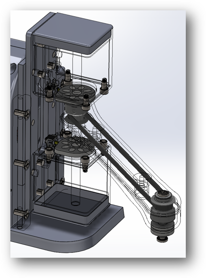
double joint_length = 4.6; // Bar-linkage length in inches
double dx, dy; // Stores distance to translate in x and y directions
double prev_t1; //Store previous angular position dtheta1 before dtheta1 is updated
double prev_t2; //Store previous angular position dtheta2 before dtheta1 is updated
double dtheta1 = M_PI; //angular position for stepper 1; by default set to dtheta1 = pi rad (starting position)
double dtheta2 = M_PI / 2; //angular position for stepper 2; by default set to dtheta2 = pi/2 rad (starting position)
int x_val, y_val; //analog readings from joy-stick for x/y axis.

int MS1 = 7; //Declare microstepping pins
int MS2 = 8;
int MS3 = 9;
int MS4 = 10;

// pushbutton pin
const int buttonPin = 2; //button pin reading input from servo button on controller
// servo pin
const int servoPin = 13;
//Reading button state of buttonPin
int buttonState;

Servo servo1;

//create a variable to store a counter and set it to 0
int counter = 0; //counter to keep track of position of servo


void setup() {

delay(5); // Wait for EasyDriver wake up

servo1.attach (servoPin); //Attach servo to pin 13

// Set up the pushbutton pins to be an input:
pinMode(buttonPin, INPUT_PULLUP);

// Set Max Speed and Acceleration of each Steppers at startup for homing
stepper1.setMaxSpeed(1000.0); // Set Max Speed of Stepper (Slower to get better accuracy)
stepper1.setAcceleration(1000.0); // Set Acceleration of Stepper
stepper1.setCurrentPosition(0);

stepper2.setMaxSpeed(1000.0); // Set Max Speed of Stepper (Slower to get better accuracy)
stepper2.setAcceleration(1000.0); // Set Acceleration of Stepper
stepper2.setCurrentPosition(0);

pinMode (MS1, OUTPUT); //Set microstepping pins as OUTPUT and HIGH
pinMode (MS2, OUTPUT);
pinMode (MS3, OUTPUT);
pinMode (MS4, OUTPUT);
digitalWrite (MS1, HIGH);
digitalWrite (MS2, HIGH);
digitalWrite (MS3, HIGH);
digitalWrite (MS4, HIGH);
}

void loop() {
#ifdef ServoYes //Run ServoCode if ServoYes is defined
buttonState = digitalRead(buttonPin); //read buttonpin either HIGH or LOW
if (buttonState == LOW) //if reading is LOW, increase the counter. When counter=0, keep servo at 10 degrees. When counter is 1 (button pressed again), turn servo to 40 degrees (push the shaft up)
{ // If button is pressed again (which means counter = 2), bring the servo back to default position of 10 degrees and set counter = 0.
counter++;
}
if (counter == 0) { //
servo1.write (10);
}
else if (counter == 1) {
servo1.write(40);
}
else if (counter == 2) {
servo1.write (10);
counter = 0;
}
#endif

x_val = map(analogRead(A2), 0, 1023, 1023, 0); // read joystick x-axis values; map x-values of joystick so they match the orientation of joy-stick controller
y_val = analogRead(A3); //read joystick y-axis values

if ((x_val > 500 && x_val < 520)) { //Ignore any unintentional minor movement of joystick in x-dir near the centre by setting dx = 0
dx == 0;
}
else {
dx = (x_val – 512) / 111.3; //When real movement is detected outside the 490<x<520 range, calculate the actual travel distance in x-direction.
} //111.3 is the conversion factor to change 1 point signal change to travel distance in inches. This was a quick approximation and can be improved by later groups.

if ((y_val > 500 && y_val < 520)) { //Ignore any unintentional minor movement of joystick near the centre by setting dy = 0
dy == 0;
}
else {
dy = (y_val – 512) / 111.3; //When real movement is detected outside the 490<x<520 range, calculate the actual travel distance in x-direction.
} //111.3 is the conversion factor to change 1 point signal change to travel distance in inches. This is an approximation and should be improved/recalculated, if needed, in the future.

if ((dx == 0) and (dy == 0)) { //If both dx and dy are calculated to be 0 (joystick at the centre), set angular positions of motor 1 and motor 2 to 0 and
dtheta1 = 0;
dtheta2 = 0;
}
else {
prev_t1 = dtheta1; //Otherwise use prev_t1/prev_t2 to store previous angular positions of motors.
prev_t2 = dtheta2;
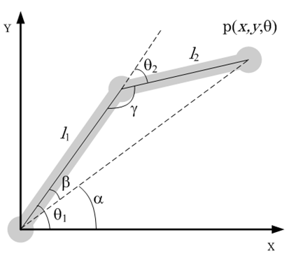
dtheta2 = acos((square(joint_length + dx) + square(joint_length + dy) – 2 * square(joint_length)) / (2 * square(joint_length))); //Calculate new angular positions with inverse kinematics equations
dtheta1 = atan2(joint_length + dy, joint_length + dx) – 0.5 * dtheta2;
}
Travel1 = ceil (dtheta1 / 0.003926991); //Convert dtheta1/dtheta2 in to the number of steps. Each step is 1/1600 of a revolution = 2*pi/1600 = 0.003926991 (in rad).
Travel2 = ceil (dtheta2 / 0.003926991); //Store steps for motor 1 and motor 2, in Travel1 and Travel2, respectively.

if ( (x_val < 500) || (x_val > 520)) { // Check if values are in the operational range of x-direction potentiometer
move_finished = 0; // Set variable for checking move of the Stepper

if (Travel1 >= -400 || Travel1 <= 1000) { // Put boundaries on how far the absolute step position can be of motor 1, and if both conditions are satisfied, then move motor 1
stepper1.moveTo(Travel1); // Set new moveto position of Stepper
}
}

if ( (y_val < 500) || (y_val > 520)) { // Check if values are in the operational range of y-direction potentiometer
move_finished2 = 0; // Set variable for checking move of the Stepper

if (Travel2 >= -400 || Travel2 <= 1000) { // Put boundaries on how far the absolute step position can be of motor 2, and if both conditions are satisfied, then move motor 2
stepper2.moveTo(Travel2); // Set new moveto position of Stepper
}
}

if (Travel1 >= -400 && Travel1 <= 1000) {
// Check if the Stepper 1 has reached desired position
if ((stepper1.distanceToGo() != 0)) {
stepper1.run(); // Move Stepper 1 into position
}

// If move is completed display message on Serial Monitor
if ((move_finished == 0) && (stepper1.distanceToGo() == 0)) {
move_finished = 1; // Reset move variable for stepper 1
}
}

if (Travel2 >= -400 && Travel2 <= 1000) {
// Check if the Stepper 2 has reached desired position
if ((stepper2.distanceToGo() != 0)) {
stepper2.run(); // Move Stepper 2 into position
}

// If move is completed display message on Serial Monitor
if ((move_finished2 == 0) && (stepper2.distanceToGo() == 0)) {
move_finished2 = 1; // Reset move variable for stepper 2
}
}
}

I would say the biggest change that should of been made was using servo motors instead of stepper motors that would of made the code simpler. 

Testing

This is a section that anybody with experience would tell you is the most critical part of a design. As we test you can conduct failure analysis and optimization in order to create a better product. This is where you know if your product works, which I think is very important. This is a reason I find myself drawn to Quality Management, performance and designing with quality in mind. Creating a great product that satisfies your customers needs are important to a company’s long term success. 

Design Show

Our set up in the design show, show casing our prototype to potential clients of our client. Also to the judges that would ultimately declare us winners.  

Team mate dressed sharply to help present. 

Competitors doing last minute changes to their designs.